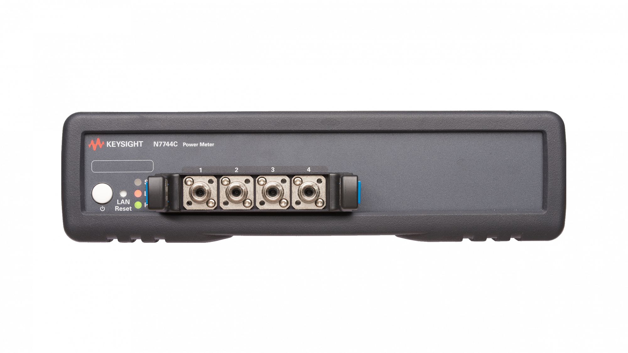
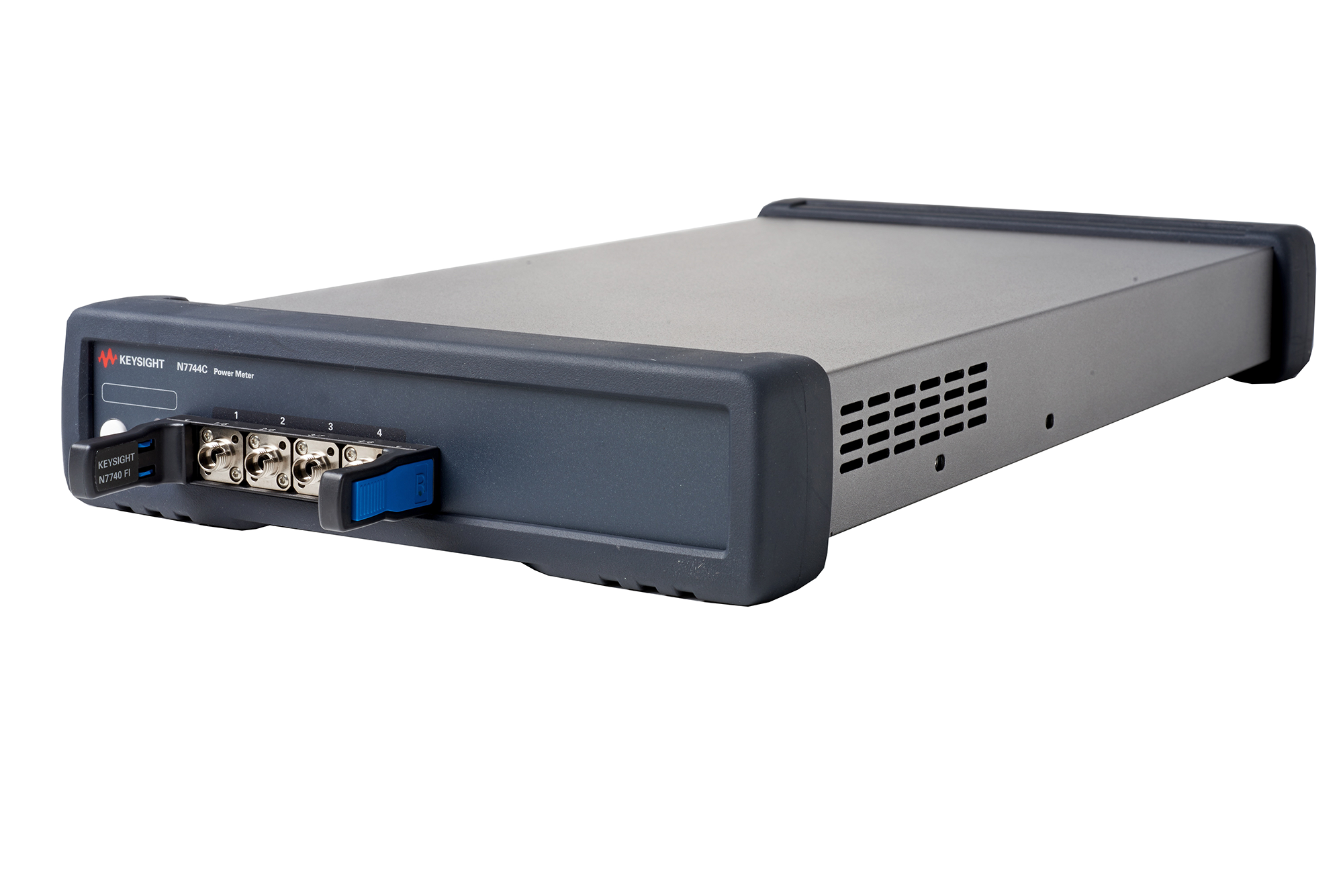
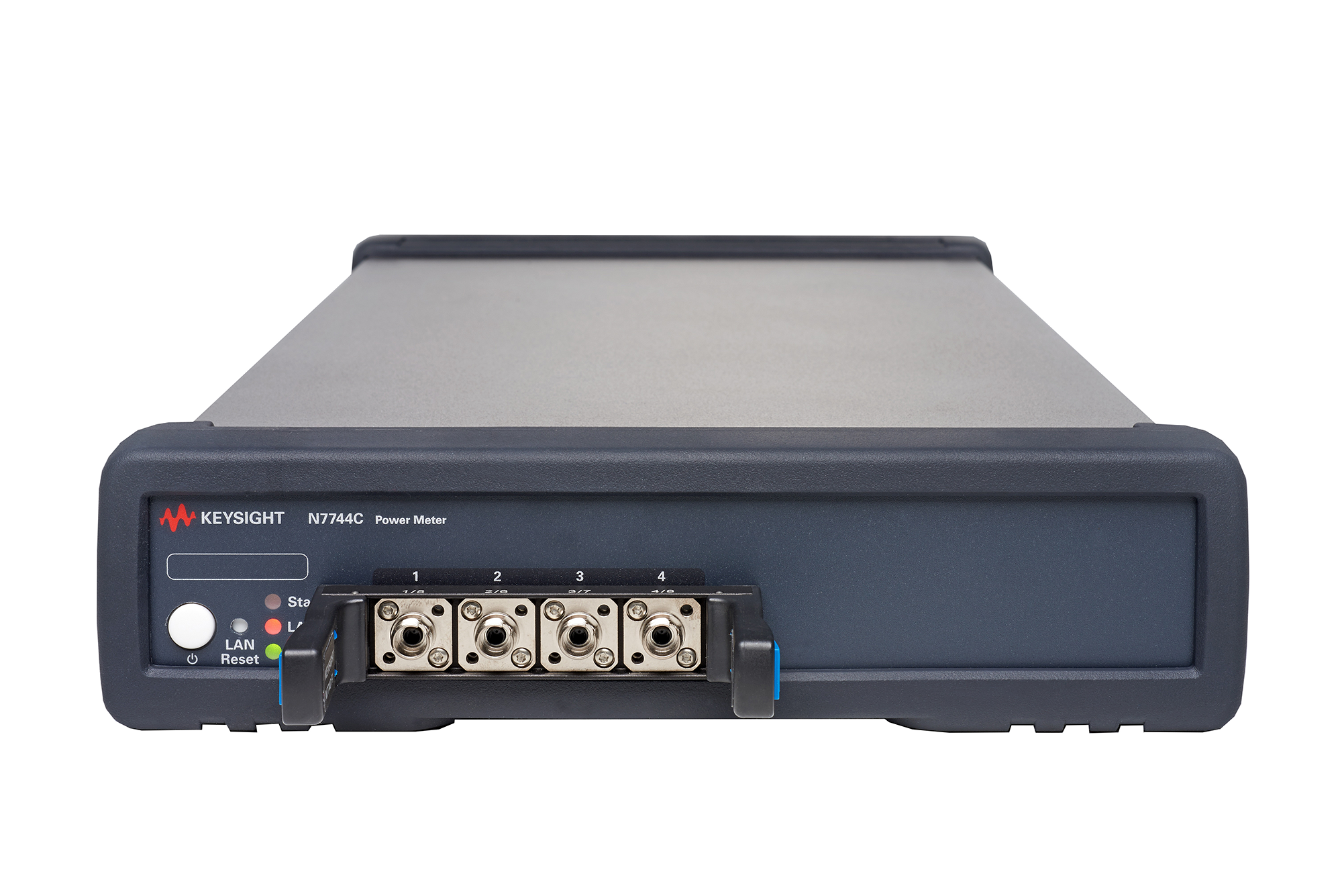
N7744C был дополнительно оптимизирован для обеспечения высокой пропускной способности измерений при характеристике оптических многопортовых компонентов, например, мультиплексоров, разветвителей PON, селективных переключателей длины волны (WSS) и ROADM. Высокоскоростной сбор данных измерений, более быстрые интерфейсы данных, использование ОЗУ с двумя портами для непрерывного одновременного измерения и считывания, а также новое более быстрое переключение диапазона мощности помогают избежать ненужных задержек в процессе измерений, а также в последующей обработке.
Особенности
- Минимальное время усреднения 1 мкс и полоса пропускания до 250 кГц
- Восемь портов датчиков InGaAs с диапазоном длин волн от 1250 до 1650 нм
- Динамический диапазон до 65 дБ в развернутых и регистрируемых приложениях без измерения дальности
- Быстрое переключение диапазона мощности для сшивания 2 измерений развертки до> 80 дБ динамического диапазона
- Погрешность мощности ± 2,5%
- Низкая поляризационная зависимость <± 0,01 дБ
- Новая функция запуска порога входной мощности
| Sensor element | InGaAs | ||
| Wavelength range | 1250 nm to 1650 nm | ||
| Specification wavelength range | 1250 nm to 1625 nm (if not stated differently) | ||
| Power range | –80 dBm to +10 dBm | ||
| Maximum safe input power | +16 dBm | ||
| Data logging capability | 2 buffers per port, each with capacity for 1 M measurement points | ||
| Averaging time | 1 μs to 10 s | ||
| Applicable fiber type | Standard SM and MM ≤ 62.5 μm core diameter, NA ≤ 0.24 | ||
| Uncertainty at reference conditions 1, 3 | ± 2.5% | ||
| Total uncertainty 2, 5, 6 | ± 4.5% | ||
| Relative port to port uncertainty 1, 3, 4, 10 | Typical ± 0.05 dB | ||
| Linearity 5, 6 | ± 0.02 dB ± 3 pW at (23 ± 5) °C ± 0.04 dB ± 5 pW over operating temperature range | ||
| Polarization dependent responsivity 3, 7 | < ± 0.015 dB (1520 nm to 1580 nm) Typical < ± 0.01 dB (1250 nm to 1580 nm) | ||
| Spectral ripple (due to interference) 9 | < ± 0.01 dB (1520 nm to 1625 nm) Typical < ± 0.01 dB (1250 nm to 1520 nm) | ||
| Drift 4 | ± 9 pW | ||
| Noise peak-to-peak (dark) 3 | < 7 pW (1 s averaging time, 300 s observation time) | ||
| Noise 2σ 3 (100,000 samples) | Averaging time: 1 μs |
25 μs Typical |
1 ms |
|
PM range –30 dBm –20 dBm –10 dBm 0 dBm +10 dBm |
Typical <0.1 nW <1.5 nW <6 nW <60 nW <600 nW |
<0.025 nW <0.15 nW <0.5 nW <4 nW <40 nW |
Typical <0.005 nW <0.02 nW <0.08 nW <0.8 nW <8 nW |
| Port separation 5 | > 85 dB (CW, one neighbor port with 0 dBm) |
| Port separation, dynamic 5 | Typical > 70 dB (one neighbor port with 0 dBm in 0 dBm power meter range) |
|
Frequency response –30 dBm range –20 dBm range –10 to +10 dBm range |
3 dB cutoff frequency at 1 μs averaging time, typical 10 kHz 130 kHz 250 kHz |
| Return loss 8 | > 50 dB (1520 nm to 1580 nm) Typical > 57 dB (1280 nm to 1580 nm) |
1 Reference conditions: Single mode fiber SMF 9 μm. Power level: –20 dBm to 0 dBm. On day of calibration (add ± 0.3% for aging over one year; add ± 0.6% for aging over two years). Spectral width of source < 10 nm full width half maximum (FWHM). Wavelength setting of power sensor corresponds to source wavelength ± 0.4 nm.
2 Operating conditions: Single mode fiber SMF. For multimode fiber, typical. Within one year of calibration; add ± 0.3% for second year. Spectral width < 10 nm FWHM. Wavelength setting of power sensor corresponds to source wavelength ± 0.4 nm.
3 Ambient temperature (23 ± 5) °C.
4 Temperature constant within ±1 K after zeroing.
5 Excluding noise and offset drift.
6 Power range –60 dBm to +10 dBm.
7 Straight connector, SMF.
8 Connector 8° angled, ceramic ferrule, SMF.
9 For constant state of polarization, source linewidth < 100 MHz, angled connector 8°, wavelength range 1520 nm to 1625 nm. Typical for 1250 nm to 1520 nm. Add ± 0.01 dB typical within specification wavelength range for straight connector with ceramic ferrule.
10 Same 4-detector block, same wavelength.


